Simple, of course, is a category of “Famous Last Words” . . .
Some months ago, I got frustrated with yet another commercial lawn sprinkler controller having gone out, and started my web research. This was not a cheap model, but rather almost $100 from a major brand name. I had three front yard lawn circuits, one back yard, and three more garden circuits on it (garden, berries, and trees). Nothing past the fourth control would work any longer–so I did what any red-blooded American male would do, hit the search engines, and got carried away (this year’s death of the lawn is a story for another day).
I’d been hearing about raspberry pi boards for quite some time, and always thought they sounded interesting. I have a couple of old Apple ][s in the garage waiting to control a model railroad some day, and wondered what I’d need the raspberry’s power to do, but never got around to following up–until now.
So a couple of internet binges later, and I found myself ordering the latest Raspberry Pi Zero W. Gosh, it costs twice as much ($10 instead of $5) as the basic Zero, but it has roughly the specs of a late ’90s workstation, and built in wifi and bluetooth.
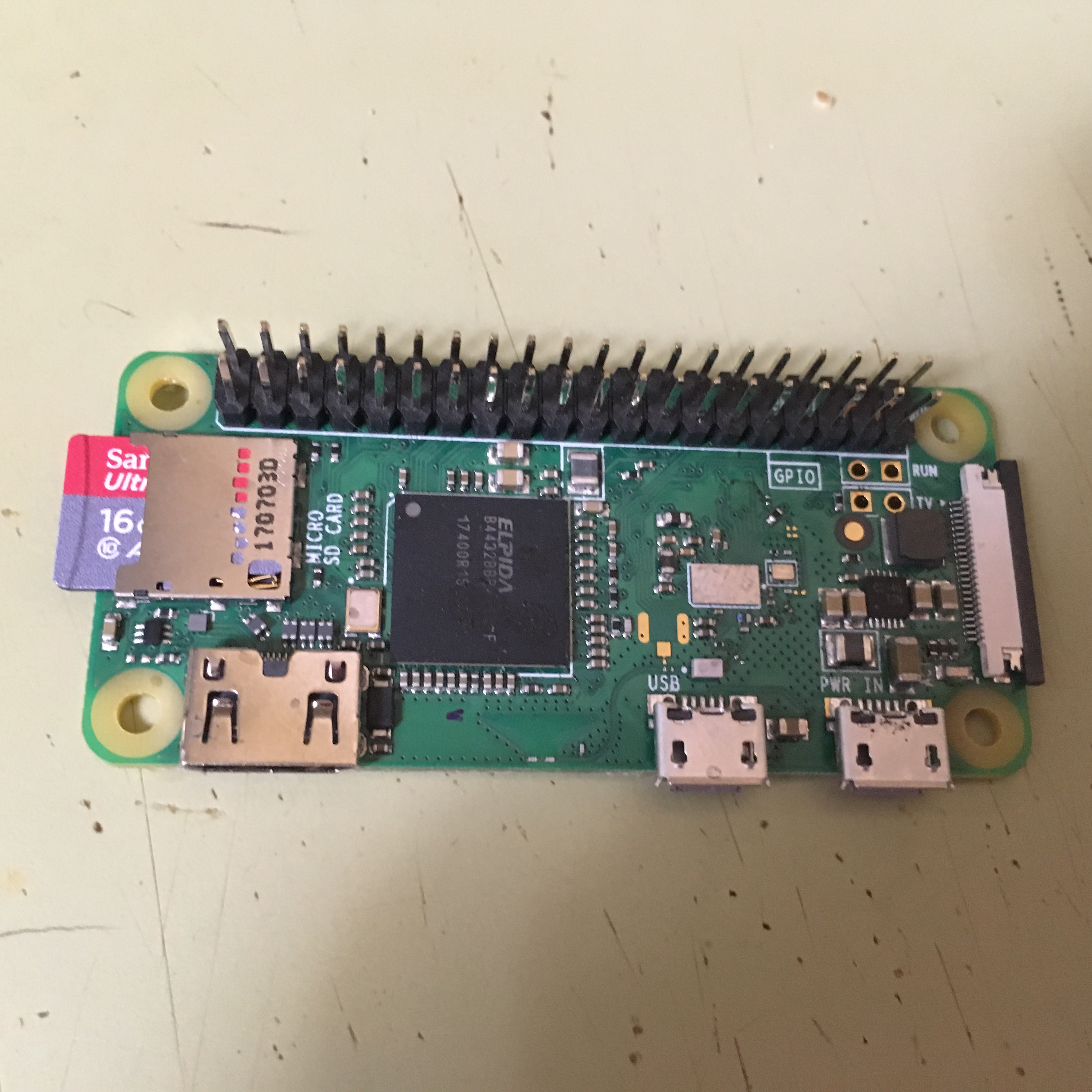
So with close to $100 later for the nice folks at adafruit, my $10 part was on the way, along with lots of odds and ends that looked interesting.
What adafruit didn’t have was a board with lots and lots of relays. I found some on Amazon, but ultimately found this critter
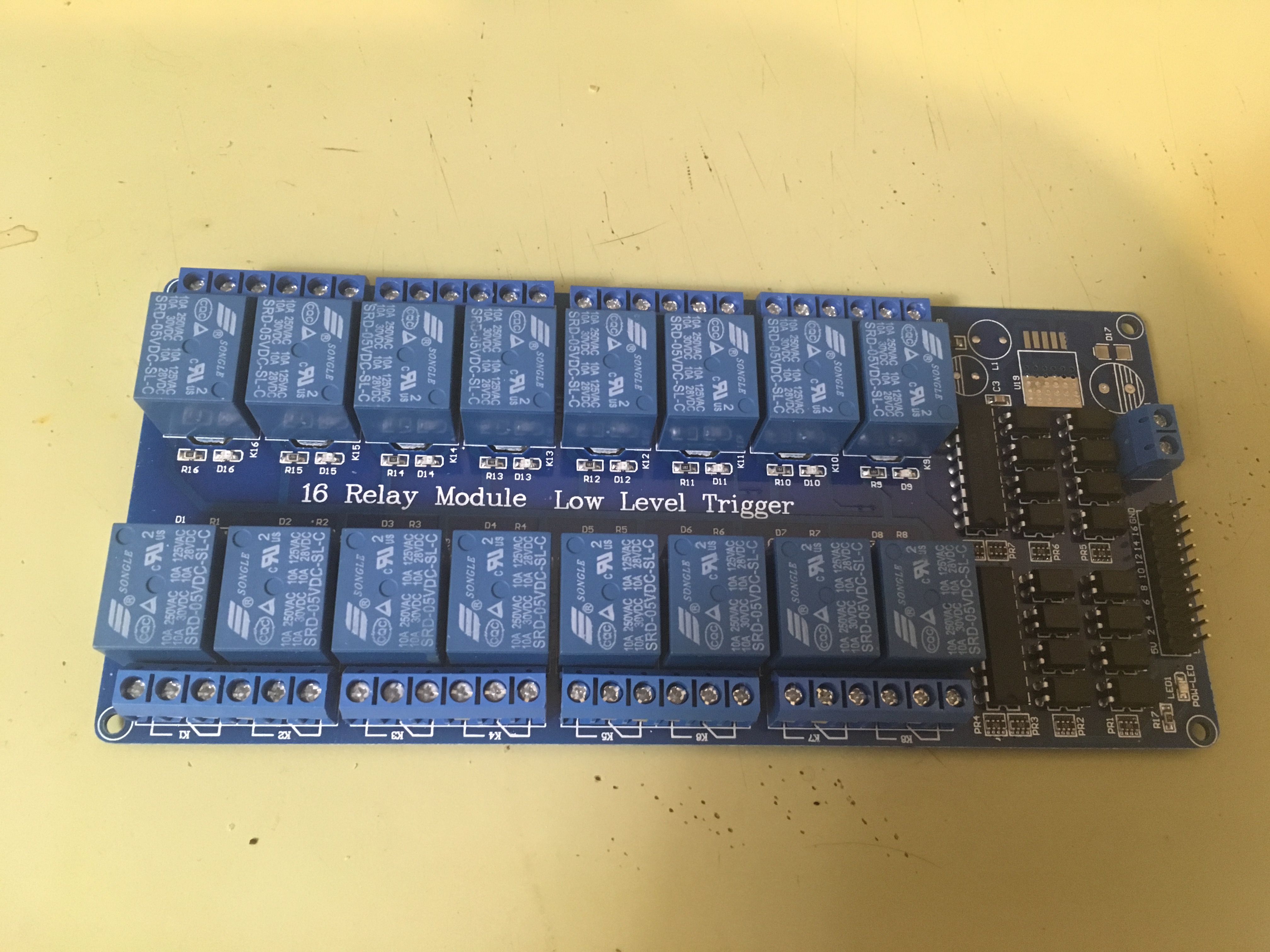
on aliexpress.com for under $12 delivered.
And *that* caused me to see so many other pieces . . . and ordered things that I hadn’t gotten to or seen on adafruit.
Which brings me to the circuit.
The Arduino is an open source project that sells harder of its design, many of which are based on the ATmega AVR microcontroller. These are 8 bit controllers equivalent to about an fast early 1980s 8 bit machine, but with more registers and a multiplication unit. These appeal to me more; I actually understood 8 bit CPUs back then, and can understand what’s going on with these ones.
And I ordered one.
OK, I ordered several.
I have some that are surface mount chips (just what was I thinking?), some on little boards that need a programmer (which I neglected to order), and at least one “nano”. It is quite similar to the Arduino nano, but uses a different USB chip–which turns out to be significant.
The nano is even smaller than the pi
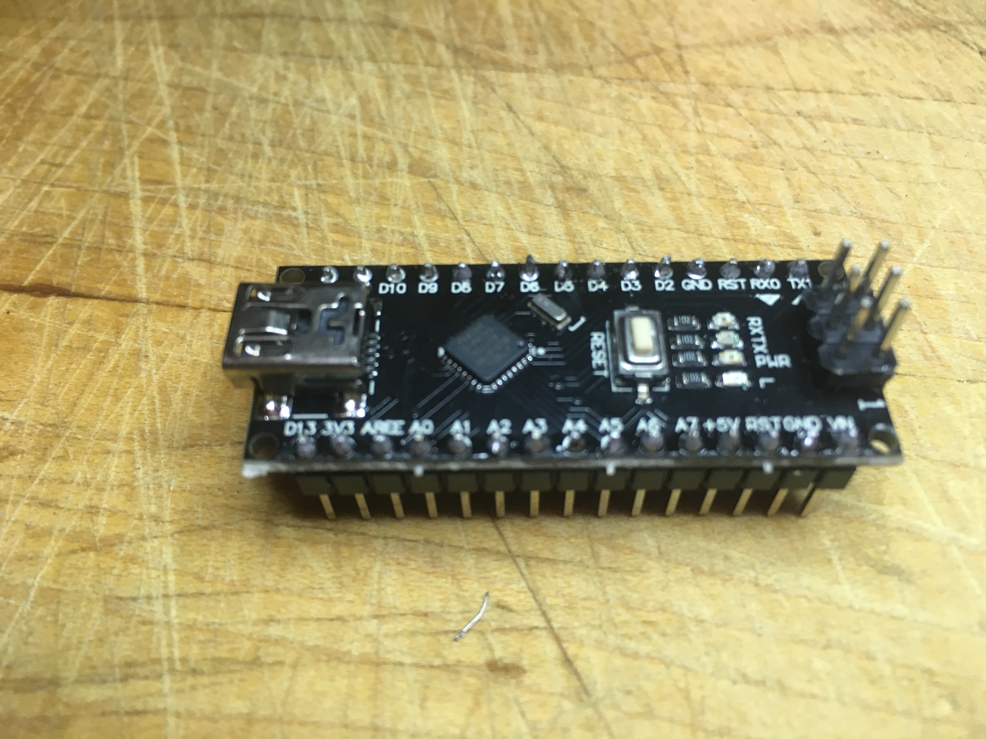
and had to be soldered together, but that, too, is for another day.
Most of the sites out there use a similar first program that blinks or flashes an LED. I found that a boring way to start, so I rigged my own circuit. I connected pushbutton switches to lines D3 and D4, and LEDs with 330 ohm resisters to lines D9 and D10.
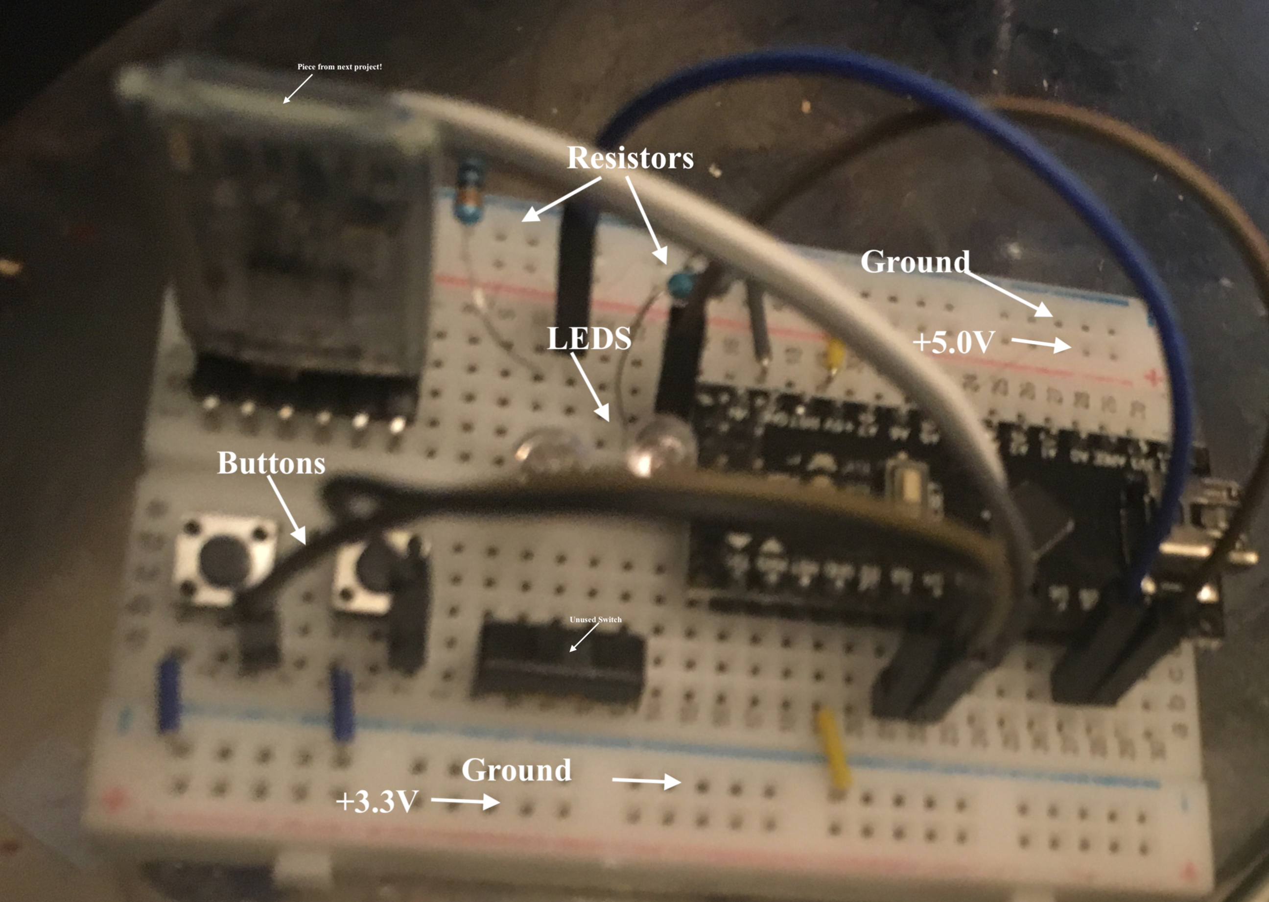
Instead of some automatic thing, or a one time change, pushing the first button lights the first LED and shuts off the second, while the second button turns on the second LED and turns off the first.
Power comes in through the microusb connector on the right. The nano regulates this to both 5v and 3.3v. A yellow jumper takes the 5v pin of the controller to the upper power rail, while the 3.3 connected to the lower (but neither is actually used). The inputs and outputs are 3.3v, but some older components and ATmegas are 5v.
The switches connect to the lower ground rail (blue) by another yellow jumper, with their other ends connected directly to the input pins. The controller has internal pulp resistors, so there is not need for my own.
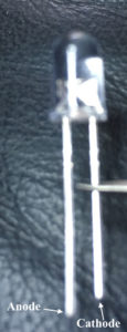
The LEDs are connected directly to output pins by jumper. This connects to the anode (positive) of the LED, while the cathode (negative) is connected to ground. When 3.3v is applied to the pin, there will be a 1.4v drop across the diode, leaving 1.9 to drop across the resistor. So 1.9v/330 Ohm is a little under 6 ma, all within what the chip can source (40ma/pin, with 500ma/total limit). Note when assembling that the anode pin is the longer one:
These controllers use a “sketch” set up on computer with the Arduino IDE. They consist of a setup() and a loop() routine. The setup() is run when the unit powers up or resets, and the loop repeats forever (or until power is cut, whichever comes first).
The setup is simple, only configuring the pins we use:
void setup() {
  // buttons on 3 & 4
  pinMode(3, INPUT_PULLUP);
  pinMode(4, INPUT_PULLUP);

  // LED on 9 & 10
  pinMode(9, OUTPUT);
  pinMode(10, OUTPUT);
}
The “INPUT_PULLUP” is an alternative to “INPUT”, and needed as we didn’t add our own pull-ups. Note that HIGH is the natural state without anything attached in this mode, so we watch for low in our code:
void loop() {
  // put your main code here, to run repeatedly:

  if (digitalRead(3) == LOW) {
    digitalWrite(9, HIGH);
    digitalWrite(10, LOW);
  }
  if (digitalRead(4) == LOW) {
    digitalWrite(10, HIGH);
    digitalWrite(9, LOW);
  }
}
And here it is running: